| Home | Accessory Kit | Marsh CD Collection | Library | Contact Us |
Chapter #19
Dr. Rife's Gating
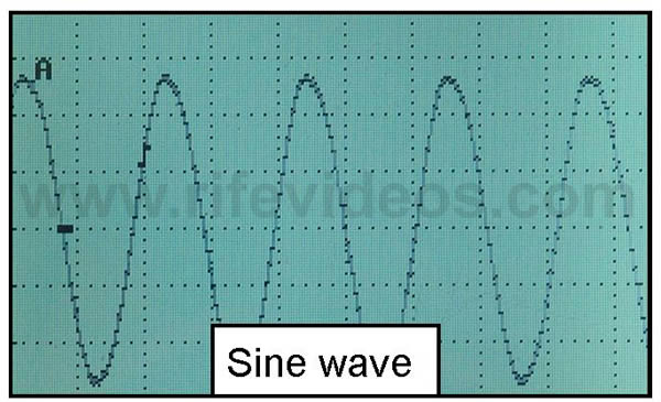
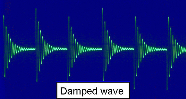
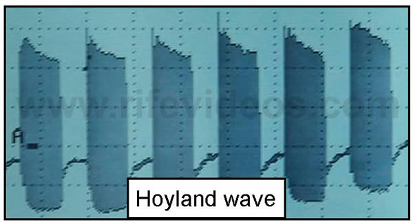
In the original 1920s/1930’s high frequency-equipment gating was used to shape the RF or high radio frequency sine wave waveform so that it had a high potential voltage rise on the leading edge. Sine waves do not have an instantaneous rise like a damped wave or a square wave. They rise like the rolling waves on an ocean. The original sine wave waveform was shaped into a damped waveform by using a single audio frequency of about 1330 Hertz. By 1936 the damped waveform was changed. The new waveform which was created looked like a square wave except it slanted down on the top of the waveform. It was basically a poor square wave. Today many call it the Hoyland wave. That is because it was Dr. Rife's engineer, Philip Hoyland, who replaced the damped wave with this new waveform in the 1936/39 Rife Ray #5 or Beam Ray clinical machine. Below you will see three photos. The first photo is of a sine wave waveform. The second photo is of a damped wave waveform. The third photo is the Hoyland wave (a poor square wave) which replaced the damped wave waveform in 1936.
By the 1950s a true square wave waveform was used instead of Hoyland’s poor square wave. So gating in the original equipment was only used to shape the sine wave waveform into a damped wave or a square wave waveform. Today gating is not used to shape the waveform as in the original equipment but it is used to add an additional pulse to the waveform by turning the waveform ON and OFF.
In the original Dr. Gruner machine which was built by Philip Hoyland, there was only one fixed low audio frequency of about 1330 Hertz used for gating. But the original 1936/39 Hoyland machine called the Rife Ray #5 or Beam Ray Clinical instrument was advanced forward in electronics and used a variable low audio frequency circuit. With this variable audio circuit, no separate gating circuit was needed because the variable low audio frequency circuit would do the same thing. It would gate or shape the high RF sine wave frequency into the shape of a square wave. This use of a variable audio circuit also produced many high RF sideband frequencies. In simple terms, the fixed gating frequency was no longer needed because of the variable audio circuit. But many people today want to have the ability to add an additional second pulse to the waveform so this is what gating is used for today. Below is a photo of a 1000 Hertz square wave waveform with no gating. The square wave duty cycle is 80%.
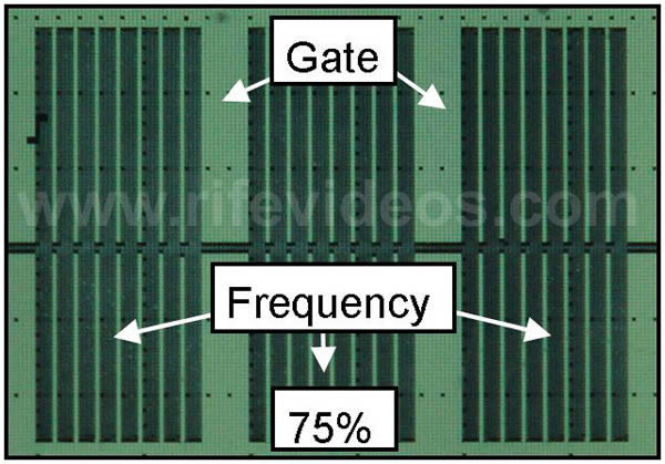
The next photo shows the same 1000 Hertz square wave waveform using a 75% gating duty cycle. The large gaps in the frequency are the gate. You will notice that the ON time of the frequency is 75% and the OFF time of the frequency is 25%.
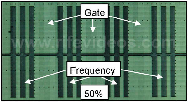
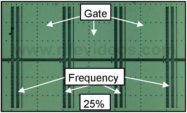
The next two photos show a 50% gate and a 25% gate.
These photos of waveforms show how gating works and how it adds an additional pulse to the waveform depending on the duty cycle of the gate. Not only can the gate duty cycle be adjusted but the cycles per second or Hertz can also be adjusted. By doing this it can vary the pulsing in the waveform. In Dr. Rife's original equipment the gate was fixed at a 50% duty cycle and the cycles per second were about 1330 Hertz.
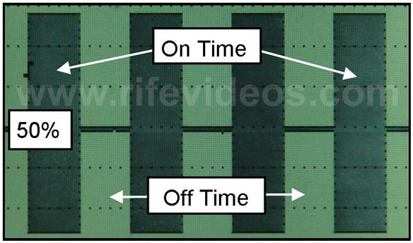
With this understanding of gating, we can now explain a few more things about gating which also need to be understood. If gating is used it will reduce the power output of any frequency being run. This power loss is in addition to the power loss with the square wave duty cycle. Below is a photo of a 50% duty cycle square wave with no gating.
In the photo above you can see by the duty cycle percentage that you only have 50% of the power in a frequency if you use a 50% duty cycle. This is due to the fact that 50% of the power is lost in the OFF time of the frequency. If you had an instrument that had a true RMS (RMS is true power) 50-watt output then you would lose 25 watts of energy because of the OFF time. There would be 50 watts of energy in the waveform, but only for the ON time.
Now if you use a 50% gate, shown in the next photo below, you would lose an additional 50% more energy in the waveform. The 50% gating duty cycle would reduce the power in the waveform to 12.5 watts of energy.
For the reasons just explained gating should only be used if you really understand what it does and how it affects the power output of the frequency you are running. Most people use gating without understanding what it is and how it works. Usually, there is sufficient pulsing in the square wave waveform without the use of gating due to the fact that the square wave waveform is already pulsing the frequency being used. If a person wants to try gating and see if it helps, having a good understanding of how gating works will help them to choose a gate duty cycle and gate rate that may work the best.
Chapter Summary: Dr. Rife used gating in his instruments. His gating was a fixed audio frequency circuit that gated or pulsed the high RF or Radio frequencies he was using. Dr. Rife's engineer, Philip Hoyland, in 1936 replaced the fixed audio circuit with a variable audio circuit. With the use of the variable audio circuit the fixed gating circuit was no longer needed. The use of gating today is an additional pulse that was not used in Dr. Rife's original equipment. This additional gating will reduce the power output in the waveform it is used with. This additional gating may or may not be helpful and only the user can determine this.
In chapter 20, "Spooky Action at a Distance" and "Quantum Entanglement" will be discussed.